


 (C:)
(C:) cs300
cs300
Virtualisation
Hardware used to dictate what software could do until virtualisation inverted the relationship. Since IBM CP-40 (1967), the story has run “abstract the machine away” $\to$ “slice it thinner” $\to$ “pack more workloads onto fewer boxes”. Hypervisors virtualise entire computers, containers isolate without duplicating the kernel, and orchestrators now manage thousands of both.
I
1.1. Hypervisor
A virtual machine (VM) is a software abstraction of a physical computer (e.g. CPU, RAM, NIC) solid enough that an unmodified guest OS boots on it. This full-hardware form is known as the system VM, as opposed to the process VM (§602#3.1). How guest instructions reach the physical CPU spans an axis. Specifically, emulation translates instructions of a foreign ISA in software (e.g. the quick emulator (QEMU) running an x86 guest on an ARM host). Whereas, virtualisation executes guest code natively on the host with shared ISA, and intercepts the instructions touching privileged machine state. So, one machine carries isolated workloads, not one application at 10-15% utilisation.
The component that performs this interception is the hypervisor (aka. VM monitor), which creates, schedules, and manages VMs. Type 1 hypervisors run directly on host hardware without an underlying OS (e.g. VMware ESXi, MS Hyper-V: Azure). Type 2 hypervisors run as applications on a conventional OS (e.g. VMware Workstation), trading performance and isolation for convenience. The kernel-based VM (KVM, 2007) reduces the hypervisor to a Linux kernel module by leveraging its scheduler, memory allocator, and device drivers, which levess it Type 1 by privilege yet Type 2 by packaging. Each VM, a guest OS and its applications, runs as an ordinary process on the host.
Popek and Goldberg (1974) formalised when such interception can rest on hardware privilege alone. It states that deprivileging the guest makes every sensitive instruction trap of its own accord, and trap-and-emulate suffices where sensitive $\subseteq$ privileged, with an instruction being i) sensitive: if it alters or depends on the machine’s configuration; and ii) privileged: if it traps outside the highest privilege level. For example, IBM’s System/370 satisfied the inclusion by design and virtualised cleanly for decades. x86 instead executes a number of sensitive instructions in user mode without trapping, and therefore, falls outside the theorem and forces software workarounds.
-
Type 1 owns the hardware, type 2 a host OS (left). KVM occupies the former's position with an OS's contents (right).
On x86 the hypervisor occupies the highest privilege level and demotes the guest kernel below it. Yet every instruction the kernel issues presumes the authority it lost. Robin and Irvine (2000) counted seventeen Pentium instructions that are merely sensitive. The POPF instruction restores the flags register yet silently discards the interrupt-flag bit when the caller is unprivileged, so a guest that disables interrupts merely believes it has. SGDT likewise leaks the host’s descriptor-table register into guest memory. The hypervisor observes neither, so trap-and-emulate has nothing to intercept.
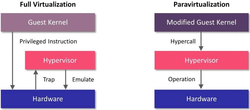
Two software workarounds emerged. VMware (1999) introduced binary translation, scanning the guest instruction stream at runtime and rewriting sensitive instructions into safe sequences that trap or emulate correctly. It stayed tractable since only kernel-mode code required translation while user-mode code ran directly on the CPU, and cached translated blocks amortised the cost. Xen (2003) took the opposite path with paravirtualisation, modifying the guest kernel to replace sensitive instructions with hypercalls to the hypervisor, which outruns translation but demands the kernel source, so an unmodified guest such as Windows cannot boot.
Intel VT-x (2005) and AMD-V (2006) eliminated both in hardware. A new non-root execution mode and a VM control structure (VMCS) make sensitive instructions VM exit regardless of privilege level, so the P-G inclusion holds again, after which the hypervisor adjusts guest state and VMRESUME returns control. The first generation nonetheless lost to binary translation on exit-heavy workloads, as a round trip cost roughly a thousand cycles against a cached block’s none, and hardware prevailed only as exit latency fell and the CPU absorbed page-table shadowing too. KVM exposes it to user space through /dev/kvm, while QEMU emulates the remaining devices.
-
Trap-and-emulate on the left, a hypercall from a modified kernel on the right.
1.2. Virtual Hardware
Just as an OS multiplexes processes onto shared hardware, a hypervisor multiplexes VMs one level below. Every resource undergoes the same three moves of abstraction, isolation, and overcommitment. For example, the virtual CPU (vCPU) abstracts the physical CPU, and the hypervisor schedules each vCPU onto the host’s cores. Moreover, overcommitment schedules $m$ vCPUs onto $n < m$ physical cores (e.g. $m/n \approx 3$ for general workloads) as VMs rarely demand full CPU at once. The guest scheduler however never sees the hypervisor preempt its vCPUs, and so suffers lock-holder preemption, where guest threads spin on a lock whose holder has been descheduled.
For memory, each VM sees its own physical address space, so translation composes two partial functions, the guest’s $\pi_g$ (guest-virtual $\rightharpoonup$ guest-physical) and the hypervisor’s $\pi_h$ (guest-physical $\rightharpoonup$ host-physical). In practice, shadow page tables materialised it but trapped on every guest update, and extended page tables (Intel EPT, AMD NPT) evaluate it lazily in hardware. Capacity can also be overcommitted. Memory ballooning inflates a driver in the guest until it surrenders frames, whereas a driverless guest leaves the host blind swapping. Kernel same-page merging (KSM) deduplicates identical pages across VMs via copy-on-write and trades a background scan for density.
A virtual disk appears to the guest as a block device yet is one ordinary host file (e.g. QEMU’s QCOW2). Under thin provisioning, a disk declared as 100 GB is an upper bound whose file grows monotonically from near zero, and the host might hold only the 20 GB written. A snapshot freezes the file read-only and chains a differencing file for later writes. Rollback is hence instant. Copy-on-write operates at cluster granularity, and a long chain pays read amplification on every lookup. Thin provisioning meanwhile lets the promised sizes sum past the host’s capacity. Guests filling their disks then exhaust it. Nonetheless, storage stays the cheapest resource to overcommit.
The hypervisor connects each VM’s virtual NIC to a virtual switch, which forwards frames among co-resident VMs at memory speed and sends the rest out the physical NIC. Most cloud VMs use VirtIO, a standardised paravirtual interface whose shared-memory rings spare the hypervisor from emulating real hardware. For bare-metal performance, SR-IOV discards the software layer. A single physical NIC presents virtual functions assigned directly to VMs, and an IOMMU (Intel VT-d) confines each function’s DMA to its VM’s memory. A virtual function however is PCIe state that no other host can reconstruct, so migratable instances stay on VirtIO.
Ultimately, a VM decomposes into runtime state and disk files. Live migration moves this data between hosts, copies memory in rounds as the VM runs, and briefly pauses to transfer the final dirty pages and switch execution. Given that the rounds converge only while the transfer rate exceeds the dirtying rate, if the inequality fails, then throttling the guest restores it. Post-copy inverts the pre-copy rounds, resumes on the destination, and faults pages on demand. A network failure mid-move strands state on both hosts and destroys the VM, so pre-copy stays the default. Hourly rental of such machines became cloud computing, e.g. AWS’s elastic compute cloud (EC2, 2006).
-
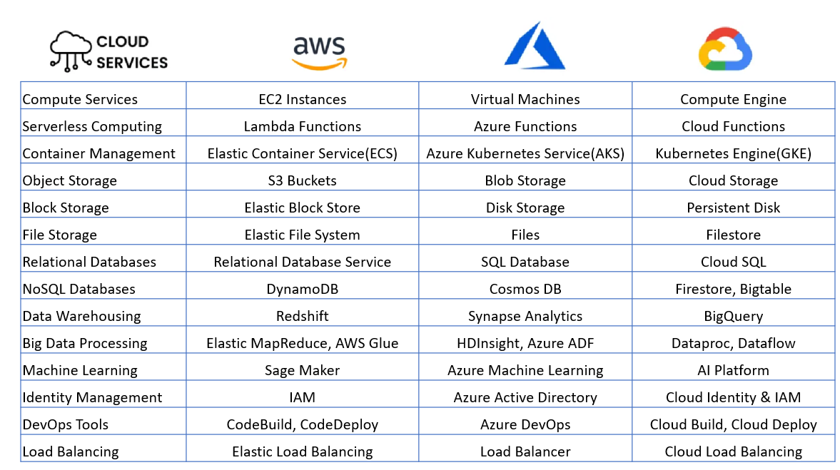
Parallel service offerings across AWS, Azure, and GCP.
1.3. Remote Machine
A cloud instance is a VM rented on provider hardware. Launching one reduces to three parameters, an image, a size, and a key pair. The provider only returns an IP address. That is, the machine exists only over the network without GUI console, and ownership barely begins by a remote login (e.g. ssh -i key.pem ubuntu@203.0.113.7), where later act passes through the same channel (e.g. deploying, debugging, rebooting). The rental of raw machines forms the cloud’s lowest rung, known as infrastructure as a service (IaaS), and one can easily find an amazon machine image (AMI), the AWS-specific form of the image for whom to launch a writable virtual disk with a preinstalled OS.
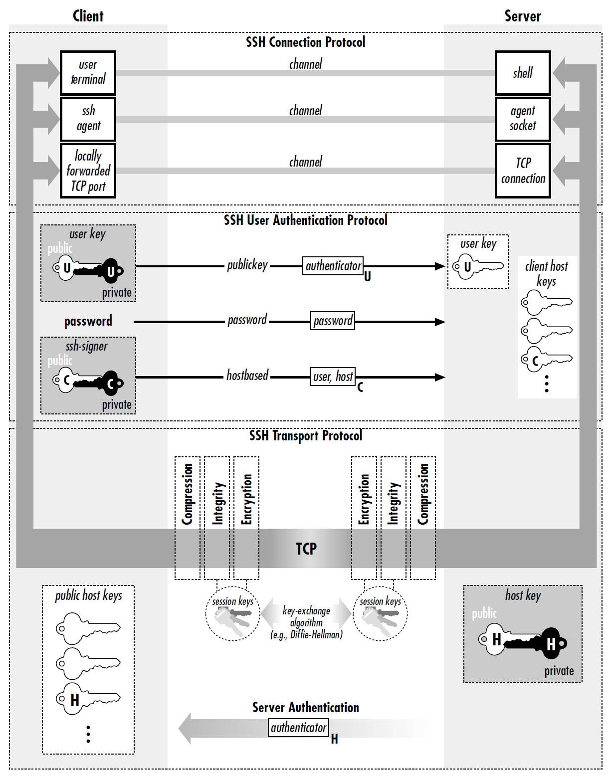
Telnet (1969) had sent every login in cleartext for anyone on the path to read. Secure shell (ssh, 1995) replaced it with an encrypted shell, whose server half ssh daemon (sshd) ships listening on TCP port 22 in every cloud image. Running ssh connects to it, the pair negotiate a session key, and sshd starts a shell (§603#2.2) on the remote machine, so the local terminal drives a remote process with every keystroke and reply encrypted in transit. As with pthreads and NPTL (§604#2.2), SSH is the protocol and OpenSSH (OpenBSD, 1999) the implementation that prevailed by adoption. Its ssh, sshd, and ssh-keygen are the programs (§602) one invokes in practice.
- …
The trust model inverts TLS’s (§605#3.4) as no certificate authority vouches for both ends. Each side instead generates a key pair and hands over its public half. The client’s lands out of band in the instance’s ~/.ssh/authorized_keys before the first login. The server holds its own pair, the host key generated at first boot, and sends the public half inside the handshake. Its fingerprint is accepted at the client’s first connection, the key then stored in ~/.ssh/known_hosts to validate the server thereafter. Under this setup, both proves possession by signing a nonce with the private half, which never travels, and a mismatch signals a different machine at the address or interception.
A single connection multiplexes independent channels, and the one of type session executes exactly one request, i) shell: a remote shell in the local terminal, ii) exec: a single scriptable command (e.g. ssh host ‘docker compose up -d’), iii) subsystem: a named service (e.g. sftp). The same protocol also carries files via secure copy (e.g. scp data.csv gpu-box:) or remote sync (rsync). Moreover, ssh forwards ports via -L (local) and -R (remote), and reach private hosts via -J (jump) through a bastion. For example, a data scientist might bind a Jupyter server to the gpu-box’s loopback, and ssh -L 8888:localhost:8888 surfaces it locally because the destination resolves remotely.
Note that where SSH forwards the $\text{L}7$ connections a user enumerates, a virtual private network (VPN) routes at $\text{L}3$. The client installs a virtual NIC whose packets travel encrypted to a gateway behind the firewall that drops unsolicited inbound traffic, so the machine joins the private network, internal DNS resolves, and every application works unchanged. The two compose rather than compete, since a VPN admits a device onto the network, whereas an SSH key authenticates a user to one machine’s shell. In either case, the unit of deployment remains the whole VM, whose image ships an OS per application, and packaging the application alone stays a separate problem.
-
The transport layer authenticates the host and derives session keys, the next authenticates the user, and the last multiplexes channels.
II
2.1. Container
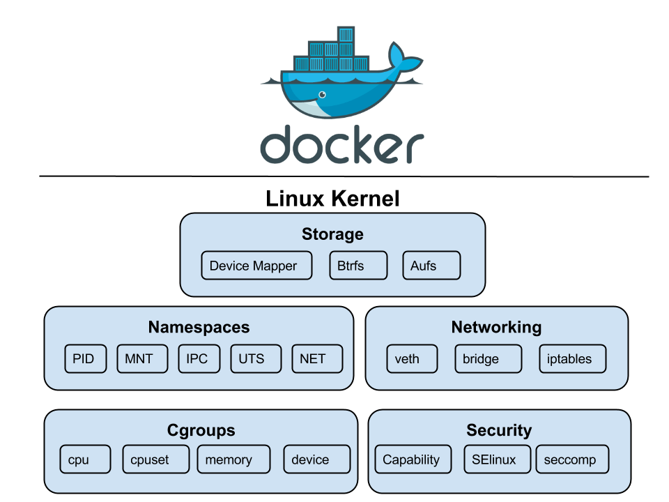
Containerisation shares a single host kernel rather than booting one per instance, and thus OS-level virtualisation reduces the unit to its application, startup to sub-seconds, and footprint to $\text{MB}$s at the cost of weaker isolation. In fact, a production-ready container generally runs inside a VM, where the hypervisor and the container separate tenants and services, respectively. The asymmetry reaches access, as the docker group yields host root by mounting the host’s root directory into a container, while an SSH key yields one VM’s own root. So, the container is not a kernel object, but a runtime-assembled configuration of namespaces and cgroups, an ordinary process to the host.
A namespace (kernel/nsproxy.c) wraps a global kernel resource (e.g. the proc table), so processes inside see their own isolated instance, and clone() with the desired flags assembles a container from the eight types Linux provides, i) pid: provides each container a PID tree rooted at 1; ii) net: gives it a private network stack; iii) mnt: swaps the visible root filesystem via pivot_root(); and iv) user: maps the container’s UID 0 to an unprivileged host UID, enabling rootless containers. The remaining four, uts, ipc, cgroup, and time, isolate the hostname, IPC objects, cgroup root, and boot clock. A namespace, however, bounds what a process sees rather than what it consumes.
A cgroup (kernel/cgroup/) organises processes into hierarchical groups and caps its hardware resources, so precludes a single container from exhausting host memory or monopolising the CPU. The kernel enforces limits on CPU shares, memory, I/O bandwidth, and device access, with the memory limit enforced by an OOM killer scoped to the cgroup. Specifically, it throttles a container that exceeds its CPU quota yet kills one that breaches its memory cap. Born of Google’s Borg (2003), cgroups entered Linux 2.6.24 (2008), and later cgroups v2 unified v1’s fragmented hierarchies into one tree and added per-cgroup pressure stall information (PSI) for observability.
Given that namespaces bound what a process sees and cgroups what it consumes, neither bounds what it may ask the kernel to do. Three further mechanisms supply the missing bound, i) Linux capabilities: root’s authority split into roughly forty independent privileges, thus a container binds a low port without also being able to load kernel modules; ii) seccomp: every system call screened by a Berkeley packet filter (BPF) program, narrowing the reachable kernel surface to the syscalls the application truly requires; and iii) security modules (e.g. AppArmor, SELinux): mandatory policy on file, socket, and capability access, which even the container’s root cannot alter.
-
Kernel features underlying containers (5 of 8 namespace types shown).
2.2. Docker
Isolation itself was old, running from FreeBSD jails (2000) and Solaris Zones (2005) to Linux’s LXC (2008). Yet none made a workload shippable while dependency packaging remained manual. Docker (2013) resolved it with a declarative, layered image model, where an image on disk is an immutable filesystem (fs) template, built once to serve many workloads. A dockerfile prescribes the image’s rootfs through FROM, RUN, and COPY steps, each yielding a content-addressed read-only layer (i.e. fs diff), so identical layers are stored once and skipped on pulls. That is, a Dockerfile captures the machine’s setup as text, versioned and rebuilt rather than maintained by hand.
Every FROM chain bottoms out at scratch, an empty image that a distro’s userland enters as a plain tarball of files. What enters above it varies by need, from a full distro userland (ubuntu, ~78 MB) through busybox-based alpine (~7 MB) down to distroless images holding libc and the application binary alone. Formally, what an image bundles is a program’s transitive dependency closure cut at the system call boundary (i.e. a userland but never a kernel). The open container initiative (OCI) standardises image and runtime specifications to make images portable across compliant engines, and registries such as docker hub and elastic container registry (ECR) distribute them.
At build time, layer immutability decides what is recomputed. Each instruction’s cache key derives from its parent layer’s digest and the instruction itself, with a checksum of the copied files for COPY. A change at one step gives its layer a new digest, every later key inherits it through its parent, and the cache misses from that point down. This is also why Dockerfile order is structural rather than stylistic, as placing dependency manifests before application source confines a rebuild to the final steps. A RUN key is the command string rather than its effect, however, leaving RUN apt-get update to reuse a stale layer until an earlier step changes or –no-cache forces re-execution.
Immutability also decides what the image ships. A layer holds the files a step leaves behind rather than the commands it ran. Deleting a file in a later step hence removes nothing, because the new layer only adds a whiteout marker that masks the file, while its bytes remain in the earlier layer. Cleanup therefore belongs inside the instruction that creates the artefact (e.g. RUN apt-get install … && rm -rf /var/lib/apt/lists/*). Multi-stage builds answer the same problem structurally, where a FROM … AS builder stage compiles and a later stage copies only the artefact via COPY –from into a minimal base or scratch, hence neither toolchain nor OS enters the shipped image.
-
The client only talks to the daemon, which pulls from the registry and runs containers.
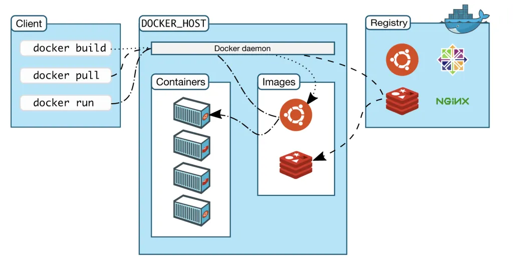
At runtime, Docker turns an image into a container, an isolated process running the image’s CMD, such as [“python”, “-m”, “app.main”], atop one writable layer. The CLI sends HTTP requests (e.g. build, run) to the docker daemon via its REST API (§605#4.2) over a Unix socket (§603#3.1) or TCP. On docker run, the daemon delegates containerd, whose snapshotter stacks the writable layer over the image layers with OverlayFS. Runc, the OCI reference runtime, then creates the namespaces with clone(), applies cgroup limits, and starts the entrypoint as PID 1. On non-Linux hosts, Docker desktop runs a hidden Linux VM whose OS is LinuxKit, a minimal distro assembled for the tasks.
The writable layer is what keeps the image immutable, but it still fails persistent state in both permanence and performance. A container lives only while its PID 1 does, docker rm deletes the stopped container with its writable layer, and the next redeploy erases any library installed into the layer (e.g. via docker exec app apt-get install curl). This erasure enforces immutable infrastructure, the discipline of replacing a running instance rather than patching it, so every environment change (packages, libraries, config) ships in a rebuilt image. A redeployment is then done by rm-and-run from the rebuilt image. Data however follows from no recipe and must survive elsewhere.
In contrast, performance fails when a container modifies a file held in a read-only layer. Specifically, the file cannot change in place, and so OverlayFS performs a copy-up which duplicates it into the writable layer before the edit applies. This copy however spans the entire file even for a one-byte change. For instance, when an application issues INSERTs into a multi-gigabyte SQLite file shipped in the image, the first INSERT copies gigabytes while later ones edit the copy at normal speed. Reads meanwhile are exempt and pass through to the lower layers untouched. Deletion likewise adds a whiteout to the writable layer, the runtime twin of the build-time mask.
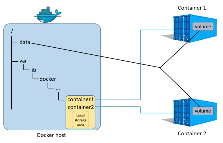
Mounts sidestep both issues by keeping data entirely outside the writable layer. In practice, Docker offers i) volumes: Docker-managed directories /var/lib/docker/volumes/ seeded from the image content at the mount point and outliving the container, for databases and other persistent data; ii) bind mounts: a chosen host path that lives with the host directory, for live code reloading; and iii) tmpfs: an empty in-memory mount that dies with the container, for short-lived secrets (e.g. API tokens). All three cover the image content at their mount point, leaving the files beneath unreachable while the mount holds, and a redeploy reattaches what the previous one wrote.
-
One host directory mounted into two containers at once.
2.3. Docker Networking
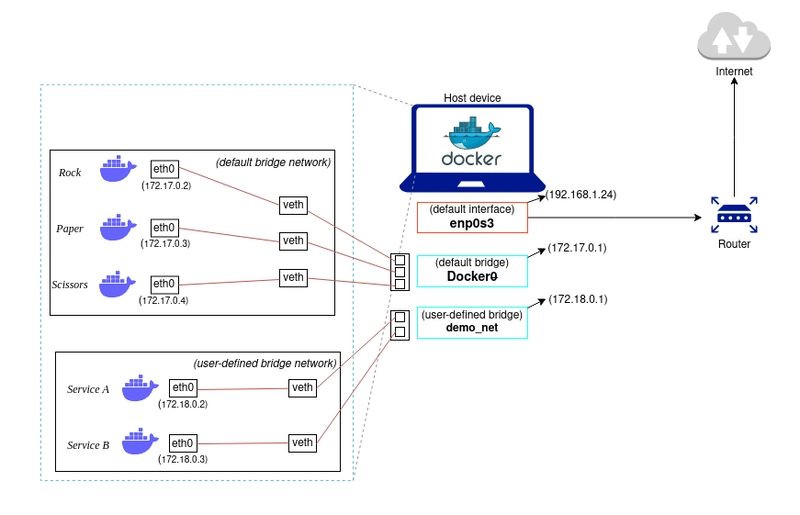
A network namespace begins with nothing but a loopback interface, and a container therefore has no path off the host until one is built for it. Docker places one end of a virtual ethernet (veth) pair inside the namespace as eth0 and enslaves the other to a software bridge (i.e. the docker0). The bridge’s address (172.17.0.1, private per RFC 1918, §605#2.1) then serves every container as its default gateway. The host thereby acts as an $\text{L}2$ switch among its containers (one broadcast domain, §605#1.3) and as an $\text{L}3$ router beyond them. Since no host elsewhere routes 172.17.0.0/16, an outbound packet from a container (e.g. 172.17.0.2) leaves masqueraded behind the host’s address.
Inbound traffic must instead be published since an external client cannot name a private IP address. For instance, -p 8080:80 publishes via a DNAT rule rewriting the destination (host:8080 to 172.17.0.2:80), while EXPOSE merely records intent. Docker also writes rules of its own via iptables into the host’s firewall, the rule list against which the kernel admits or drops every packet by its tuple $($address, port, protocol$)$. The kernel consults Docker’s entries before those a tool such as UFW administers, thus a published port stays open to the LAN even after a deny, which holds only when placed in the DOCKER-USER chain that Docker checks first.
Reaching other containers is a separate matter. The default docker0 affords $\text{L}2$ forwarding but no name resolution, so a container reaches another only by IP address, which restarts may reassign. Docker instead provides user-defined bridge networks, carrying their own subnet (172.18.0.0/16, §605#2.1) with an embedded DNS server (127.0.0.11), which resolves container and alias names to current addresses. In practice, Docker compose automatically creates one such network per project from a YAML ain’t markup language (YAML) file and starts containers in dependency order. Containers on separate bridges remain isolated, as no rule forwards between them.
The isolation hardens across machines. An $\text{L}2$ bridge is confined to its host, thus the docker0 bridges on two hosts each issue 172.17.0.0/16, and neither has a path to the other. An overlay network supplies one by wrapping container frames in UDP packets between hosts (VXLAN, §605#1.2). Wrapping costs 50 header bytes, hence the MTU of 1450. Paths that filter ICMP break path MTU discovery (§605#1.3) and full-size packets vanish, thus overlay faults surface as hangs on large responses rather than refused connections. Reachability is nonetheless the smaller half. The larger half, scheduling and repairing workloads across machines, falls to orchestration.
-
Default docker0 and a user-defined bridge, each an isolated subnet behind the host NIC.
III
3.1. Container Orchestration
A single host suffices for development, but production must schedule workloads across a cluster (a set of networked machines), restart failures, balance load, and roll out updates without downtime. Container orchestration treats the pool as a single logical compute surface and maintains a desired state (e.g. “run 5 replicas with 2 CPUs and 4 GB each”) which a control loop restores by correcting observed drift. The desired state is thus a fixed point of the reconcile map, toward which the loop drives the system anew after every disturbance, and declaring the fixed point rather than the path to it is what distinguishes orchestration from imperative commands.
Kubernetes (K8s ), built at Google on Borg, open-sourced in 2014, separates a cluster into a control plane and worker nodes. Cluster state lives in etcd, a Raft-replicated key-value store that only the API server reads or writes, so every other component watches that entry point (§605#4.2), never the store. A scheduler places pods by filtering infeasible nodes and scoring the rest. A controller manager runs one control loop per resource type, each reconciling its slice. A kubelet on each node starts its assigned pods through the container runtime interface (CRI). Managed offerings (EKS, GKE) host the control plane, typically leaving users nodes and workloads.
A pod is the fundamental scheduling unit, a group of one or more containers that share a network namespace, storage volumes, and a lifecycle. Most pods run a single container, but the abstraction allows co-locating tightly coupled containers as sidecars (e.g. a web server alongside a log collector or service-mesh proxy) that share localhost and are scheduled together. Pods are ephemeral by design, as a rescheduled pod is a new pod with a new IP and a fresh filesystem rebuilt from the image rather than the old one relocated, so whatever an application keeps locally is lost at that moment. Stateless workloads absorb this, and stateful ones do not.
-
Every arrow ends at the API server.

3.2. K8s Workloads
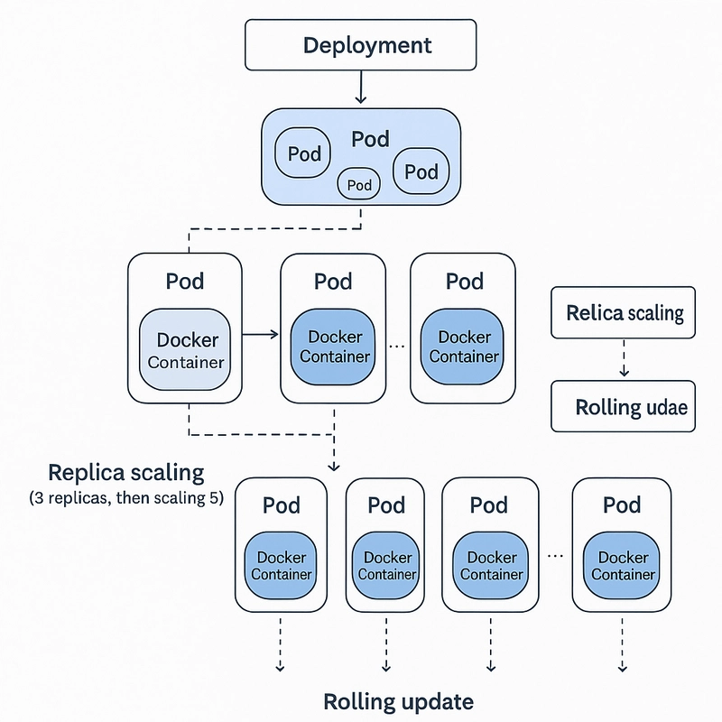
A pod alone has no self-healing, so a failed node erases its pods. Deployments close this gap for stateless applications with a replica count and a pod template, and find them by label selector over labels such as app: nginx. A Deployment acts only through a ReplicaSet, which holds one template, drives the matching pod count toward it, and replaces failures. That indirection makes updates reversible, as a rolling update shifts replicas to a fresh ReplicaSet for the new template, while the old survives at zero so rollback shifts them back. The Horizontal Pod Autoscaler resizes replicas on metrics, whereas the Cluster Autoscaler adds nodes when pods fit on none.
Not every workload tolerates interchangeable replicas. A Raft or Kafka quorum addresses members by identity and expects each to return with its log, which a ReplicaSet cannot give since its pods are anonymous and their storage dies with them. StatefulSets supply it, as each pod receives a stable ordinal name (pod-0, pod-1) and DNS record, a volume that survives rescheduling, and ordered startup and shutdown, so a rolling update replaces one member at a time. The remaining controllers vary the loop over other targets, where DaemonSets run one pod per eligible node for node agents and device plugins, Jobs run a pod to completion, and CronJobs schedule them.
Pods also need configuration and storage decoupled from the image. ConfigMaps and Secrets inject environment variables or mounted files so the same image runs unchanged across environments, though a Secret is base64-encoded rather than encrypted and is guarded only by etcd access control and RBAC until encryption at rest is configured. PersistentVolumeClaims (PVCs) request storage from the cluster and StorageClasses provision it dynamically (e.g. an EBS volume), which keeps manifests portable but binds the claim to the volume’s failure domain, so a pod whose zonal volume has no schedulable node in its zone stays Pending.
K8s namespaces (distinct from Linux namespaces) partition a cluster into logical units (e.g. dev, staging, prod) that scope resource names and access policies. A ResourceQuota caps the aggregate CPU and memory a namespace may claim, so one team’s workloads cannot starve another’s, and RBAC roles bind permissions at the same boundary, so a user or service account holds rights within its namespace and nothing beyond. Every resource is declared as a YAML manifest applied via kubectl, where kubectl apply merges the declaration into the desired state held by the API server rather than issuing imperative commands, the same fixed point the control loops then maintain.
-
Deployment drives replica scaling (3 to 5) and rolling updates.
3.3. K8s Networking
Kubernetes replaces the host-local bridge with a flat network where every pod holds a cluster-routable address and reaches any other without NAT, so a service sees its caller’s real address. The cluster must now assign cluster-unique addresses and route them everywhere, the problem CNI (container network interface) plugins solve. They divide on defaults, where Flannel encapsulates pod frames in VXLAN and pays the header cost to run anywhere, Calico advertises pod routes over BGP to travel unencapsulated wherever the underlay carries them, and Cilium programs the datapath in eBPF, which extends policy to $\text{L}7$ where Calico stops at $\text{L}3$/$\text{L}4$ and Flannel omits it.
Pod IPs change on every restart, so Services typically provide a stable virtual IP (ClusterIP) and DNS name that load-balance across whichever pods currently match a label selector. On each node kube-proxy programs that mapping into iptables rules, whose count grows with services and endpoints, so newer clusters move to its nftables mode or an eBPF datapath that hashes to a backend in constant time.
Reaching a Service from outside the cluster is a separate ladder, where NodePort opens the same port on every node from a default 30000-32767 range yet offers no single address to publish, LoadBalancer puts a cloud load balancer in front of those ports and so supplies the address at the cost of one balancer per Service, and Ingress (or its successor the Gateway API) terminates TLS and routes on hostname and path so that many Services share one balancer, implemented by controllers such as Nginx Ingress or Traefik.
From hypervisors that virtualise entire machines, to containers that share a kernel, to orchestrators that schedule across clusters, each layer trades isolation for density and abstracts the one below it. MicroVM runtimes (e.g. AWS Firecracker, which underpins Lambda and Fargate) and sandboxed runtimes (e.g. gVisor’s user-space kernel) occupy the middle ground, and restore per-workload hardware isolation at near-container startup cost. The unit of deployment has moved from a physical server to a VM to a container to a pod, but the underlying goal is unchanged, to pack more workloads onto fewer boxes.
 me.bat
I gathered words solely for my own purposes without any intention to break the rigour of the subjects.
I also prefer eating corn in spiral .